


Smallpeice Trust
Sponsor
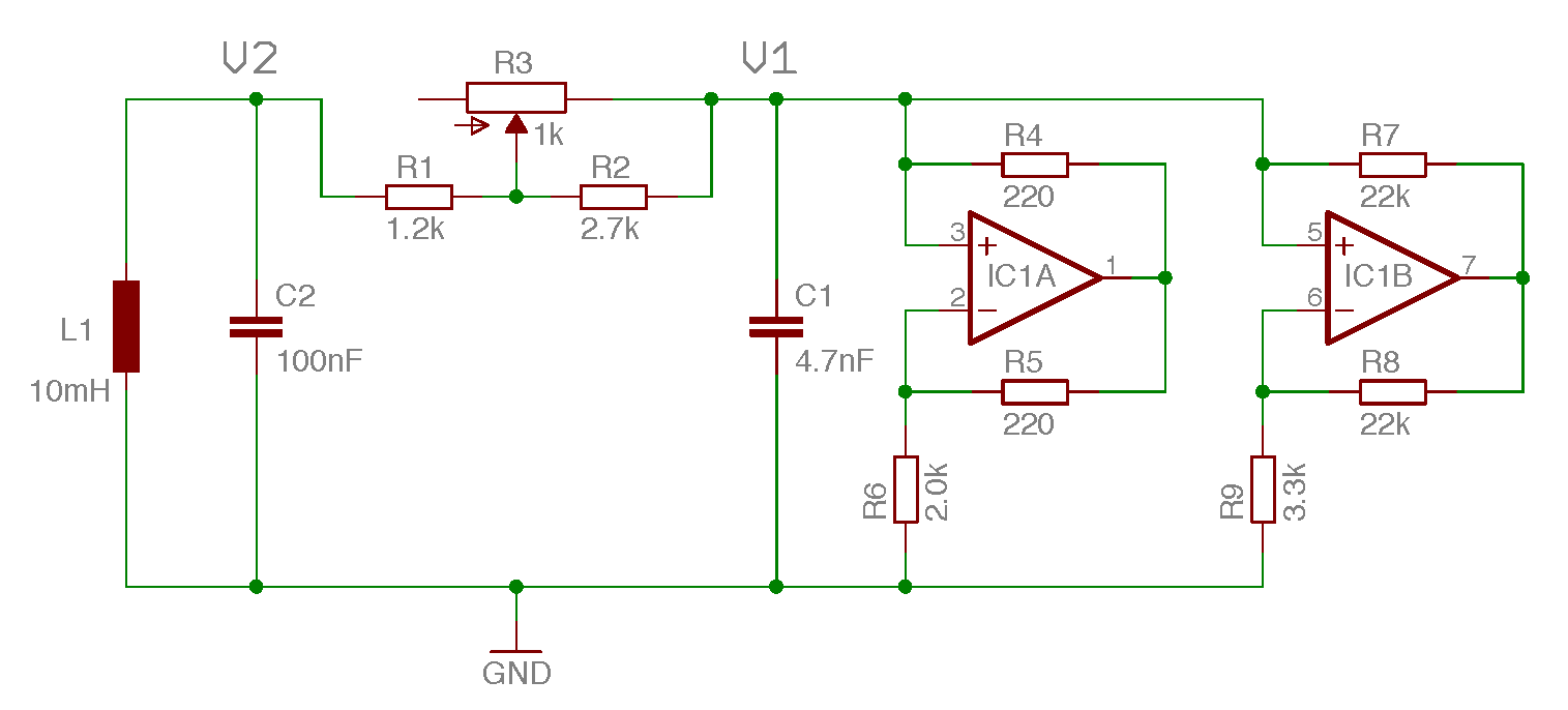
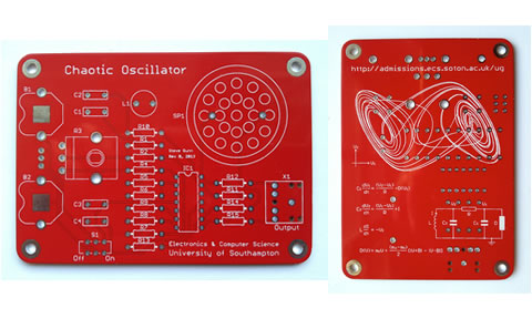
The Main Circuit
To build the circuit you will require some basic electronic tools. You can obtain a reasonable set of tools from any of the main Electronic suppliers. A couple of suitable kits would be the Rapid Electronics Tool Kit plus solder (£33), or if you are on a tight budget the CPC Soldering Kit (£10). Remember, in general you get what you pay for - more expensive tools from established companies will typically last longer and perform better.
If you haven’t done any soldering before, now is a perfect time to learn! This video provides a great tutorial on how to solder.
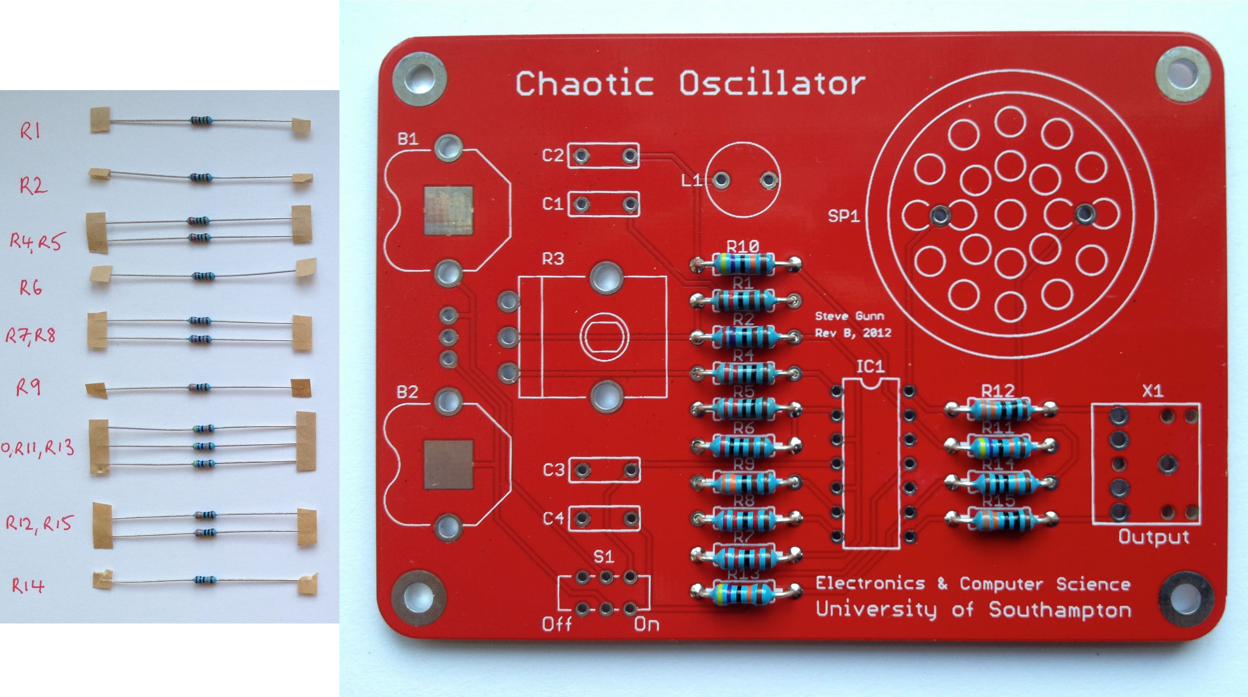
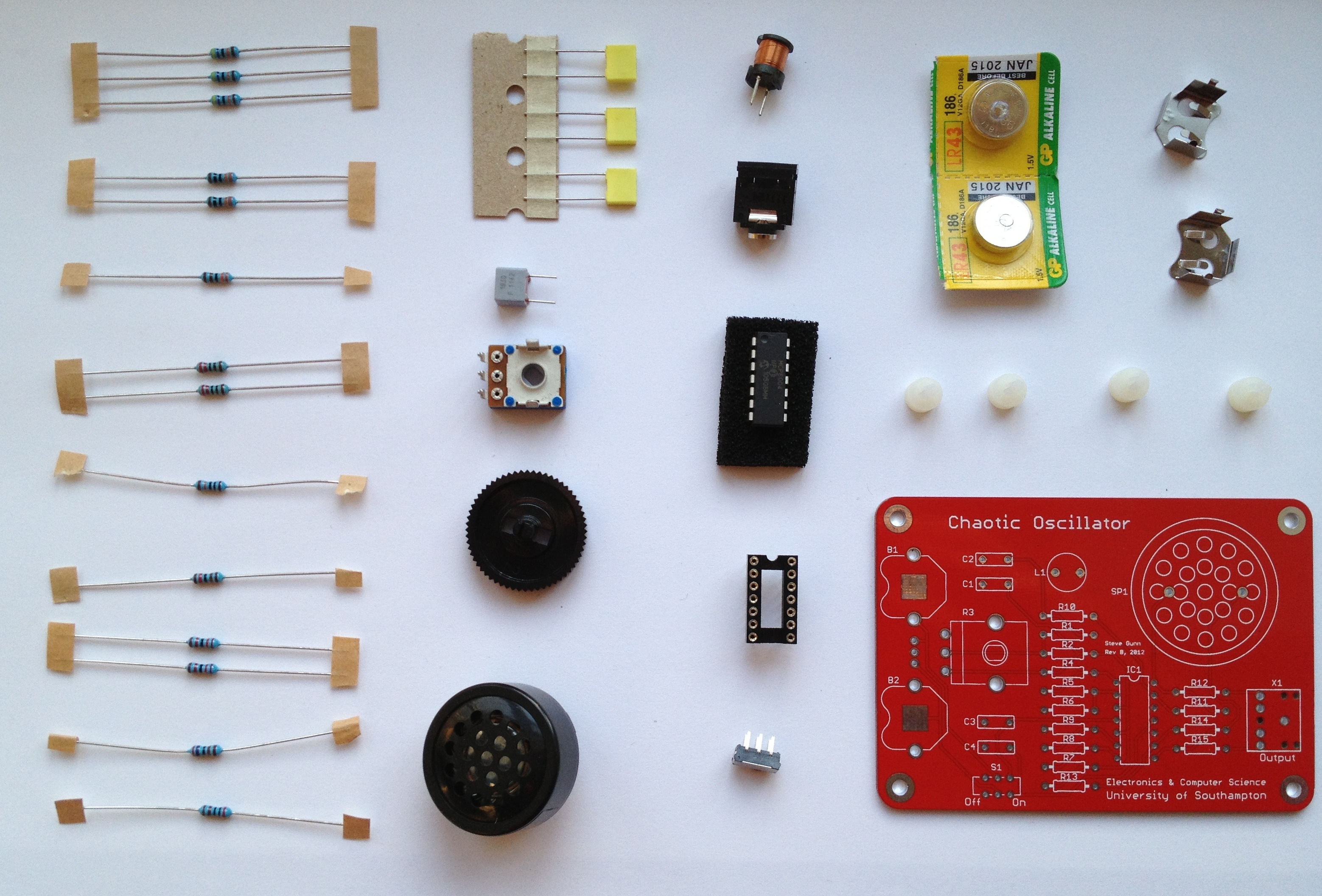
Start by fitting the fifteen resistors labelled R1-R15. Start by laying them all out on a piece of paper and labelling them according to their value. Their value is indicated by coloured bands (or could be checked with a multimeter).
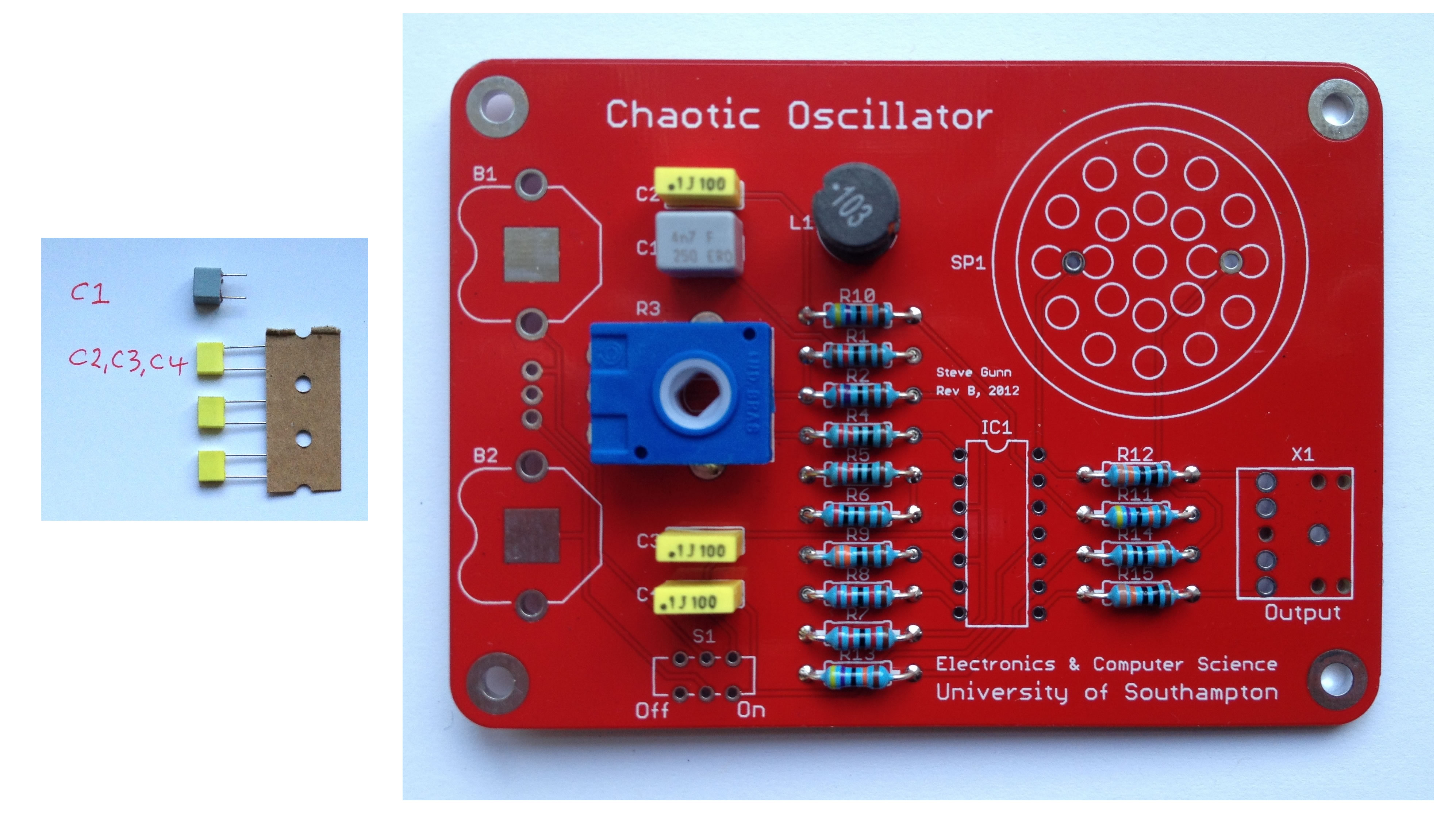
Next fit the capacitors, taking care to ensure that C1 is the 4.7nF capacitor. Then fit the inductor (L1). Finally fit the potentiometer (variable resistor) taking care to ensure that it is firmly pushed into the board before soldering.
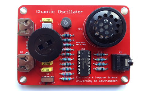
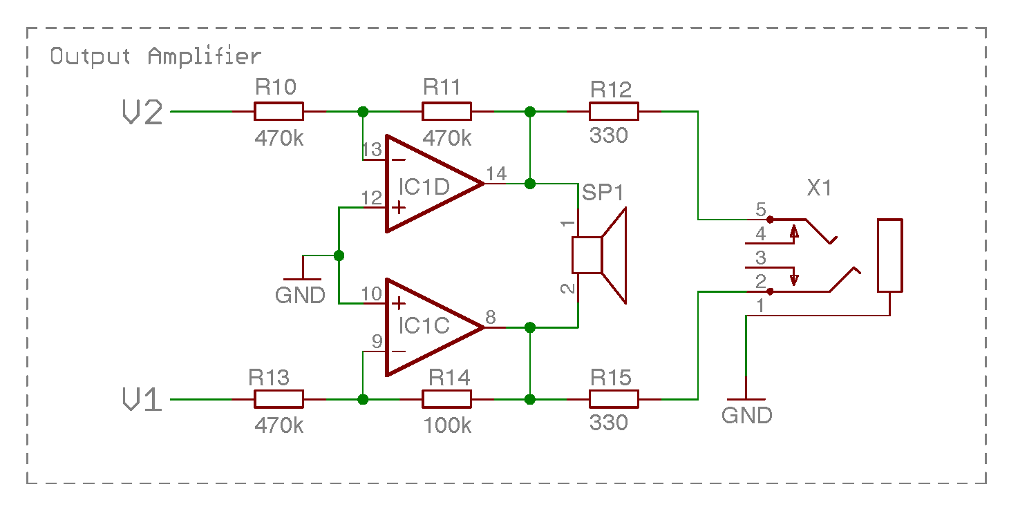
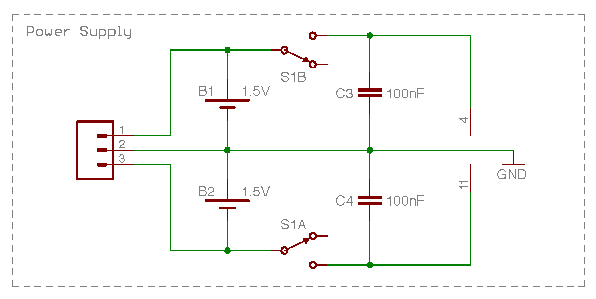
Next fit the IC socket, the battery holders (B1 and B2), the switch (S1). The speaker SP1 can now be fitted and it does not matter which way around it is fitted in this circuit. Finally fit the jack socket (X1). You have now finished the soldering aspect of the project. To finish up, fit the four plastic feet by pushing them into the holes from the underside of the board. Attach the potentiometer knob by inserting it from the top. Lastly, insert the IC taking care to ensure that the indent or dimple indicating pin 1 is in a NW orientation.
Ensure S1 is in the off position and insert the two batteries with their positive terminals upper most. Turn on the switch S1 and rotate the potentiometer. If all goes well you should hear a range of noises as the potentiometer is varied which are centred around the main frequency of 4kHz. The sound is deliberately not too loud so as not to irritate. If you wish to hear it louder you can insert a pair of earphones into the 3.5mm jack socket or connect the system to a stereo amplifier.
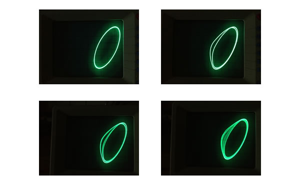
To see the real beauty of the chaotic behaviour you need an oscilloscope. Most of you probably have one, even if you did not realise it. It is possible to use the sound input on your computer as a low frequency oscilloscope which is sufficient for this exercise. Download the Soundcard Oscilloscope. This is a free program which converts the left and right channel from line in, to a two channel oscilloscope. Unfortunately, it is only available for Windows, so you will need to run it in a virtual machine if you are using a Mac or Linux. The oscilloscope is a tool to plot the dynamic behaviour of a circuit and enables us to see how voltages vary over time. Additionally, this oscilloscope enables us to display two inputs against each other in an X-Y mode revealing the nature of the chaotic attractor. Finally, it is even possible to look at the frequency content of the signals.
You will need a cable to connect your oscillator to your computer. The cable you require has a 3.5mm stereo jack plug on both ends and is sometimes shipped with iPods or music players. If you do not have one you can buy one from Rapid.
The circuit is quite sensitive to the precise component values and hence you may get some variation from the examples shown here.
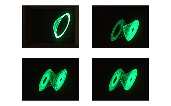
As you increase the potentiometer you should be able to hear the oscillator go through a period doubling sequence before entering chaotic behaviour.
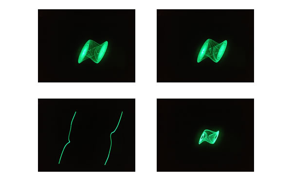
As you further increase the potentiometer you may be able to get the oscillator to show both sides of its attractor.
Further increasing the potentiometer will tend to shrink the attractor and in the limit will produce a stable (louder) oscillation around the main frequency of 4kHz.
For any enquiries, please email us at kits@soton.ac.uk.
This initiative has been developed in partnership with the UK Electronics Skills Foundation (UKESF), and with the sponsorship of organisations including the Smallpeice Trust, and support and donations from a wide range of companies, charities and other organisations.
The Logic and Arithmetic kit incorporates core electronics concepts suitable for A-level Computer Science students, in particular covering aspects of Boolean operations, logic gates and base 2 (binary) number systems.
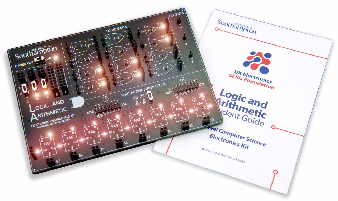
The kit is split into two sections: 'Logic' and 'Arithmetic', with Light Emitting Diodes (LEDs) used to indicate logic states throughout.
The kit is currently not available to purchase, but limited numbers are being provided to schools for free. Schools/colleges interested in receiving kits, or organisations interested in sponsoring the scheme, can join our mailing list to find out more.
We are building teaching resources around these boards, for example our accompanying set of logic problems (and solutions) and online training video. If you would like to contribute resources, please contact us.
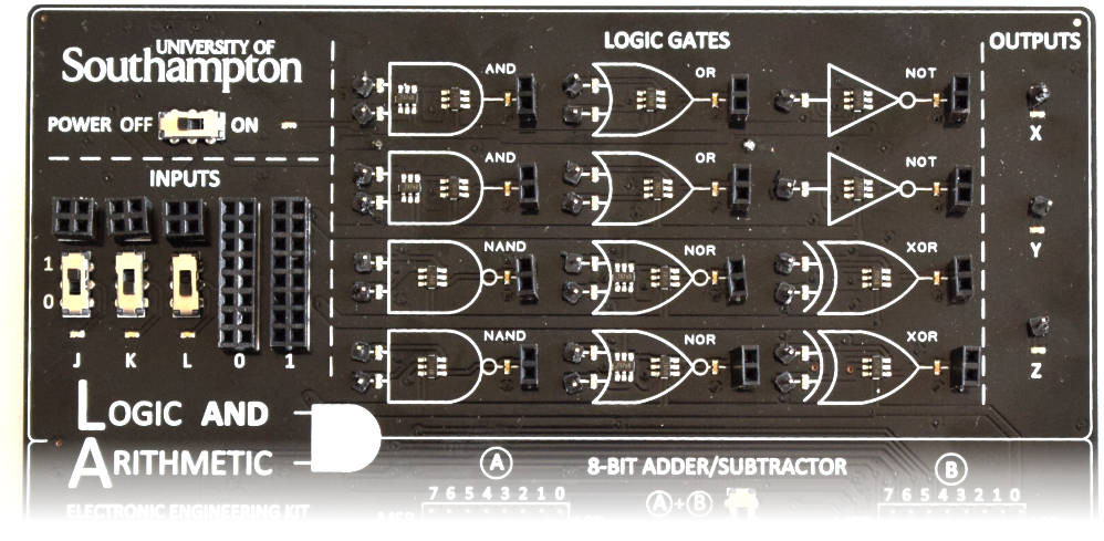
This can be used to explore Boolean operations and logic gates, and to implement simple logic functions and circuits. The board has three switchable logic inputs, a range of different logic gates (AND, OR, NAND, NOR, XOR, NOT), and three logic outputs. Orange LEDs indicate the state (logic 0 or 1) of the individual inputs and outputs of every gate.
This tutorial video walks viewers through the typical use of the Logic Section of the kit, and demonstrates how you can use it to connect inputs, logic gates and outputs together in order to implement and explore a logic problem.
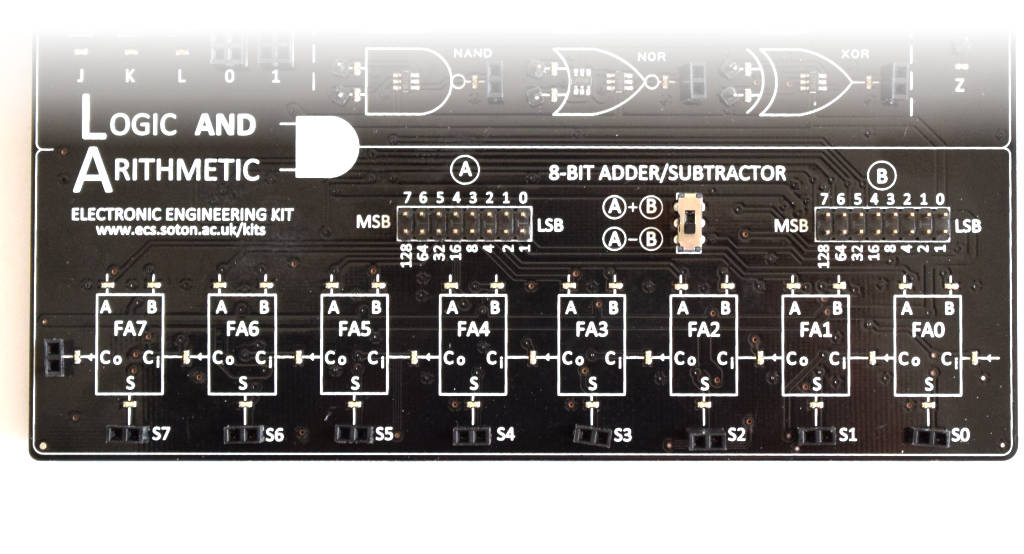
This provides an 8-bit two’s complement adder/subtractor circuit, offering the ability to perform A+B or A-B (where A and B are 8-bit binary numbers). This can be used to experiment with unsigned and signed binary arithmetic, as well as offering a different way to observe and understand binary number systems. This can even be extended to a 9-bit adder circuit, by using the Logic Section of the kit to implement a Full Adder.
This tutorial video walks viewers through the typical use of the Arithmetic Section of the kit, demonstrating how you can use it to add two 8-bit unsigned binary numbers, and add or subtract two 8-bit signed two's-complement binary numbers.
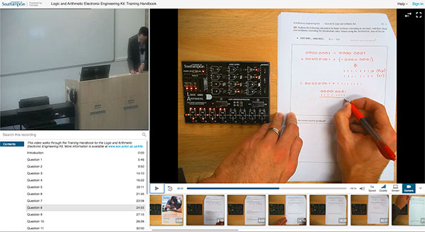
To provide training to teachers who were not able to travel to the University to attend one of our CPD workshops, we have recorded a video which walks through the Logic and Arithmetic Electronic Engineering Kit's Training Handbook.
We are keen to receive any feedback that you might have about this video. If there are parts that are unclear, or additional things that you would like demonstrated, please contact us.
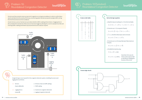
This set of Logic Problems, based on real engineering examples, is specifically designed to accompany our Logic and Arithmetic Kit.
The logic problems were created by Kiran Patel, a UKESF Scholar, while he was a student at the University of Southampton studying Electronic Engineering with Computer Systems. There are a total of 10 different problems, of increasing difficulty, with accompanying worked solutions.
If the Logic and Arithmetic board does not work, first of all:
If the kit still does not work then please email us.
It is essential that we maintain student engagement in Physics and Computer Science at A-Level as these are the gateway to engineering, hence our interest in working with UKESF and the University of Southampton to support teachers to inspire students’ interest in these subjects.
Sponsor

Supporter

Supporter

Supporter

Supporter

Supporter

Supporter
Donor
Donor
Donor
Donor
Donor
Donor
Donor
Donor
Donor
Donor
Donor
Donor
Donor
Donor
Donor
Donor
Donor
Donor
Donor
Donor
Electronics and technology play a vital role in tackling society’s biggest challenges, but at the moment, not enough young people have the opportunity to experience these subjects in an engaging way, or consider what career opportunities they could lead to.
The A-Level Computer Science Logic and Arithmetic Kit has been created by the following team from the University of Southampton and UK Electronics Skills Foundation:

Geoff is a Professor and Director of Outreach and Recruitment in ECS, and has led on the development of the A-Level Computer Science kit.

Alex is a Lecturer in ECS, and is leading on professional development activities using the A-Level Computer Science kit.

Daniel is a Lecturer in ECS, and part of the team developing the A-Level Computer Science kit.

Stewart is the CEO of the UK Electronics Skills Foundation, and has led on securing funding to get the kits into schools.
For information on when kits are available, and other developments in the project, please join our mailing list.
For any other enquiries, or to contribute resources, please email kits@soton.ac.uk.
This initiative has been developed in partnership with the UK Electronics Skills Foundation (UKESF), and with the sponsorship of organisations including the Smallpeice Trust, and support and donations from a wide range of companies, charities and other organisations.
The Music Mixer circuit board incorporates core electronics concepts suitable for A-level Physics students.
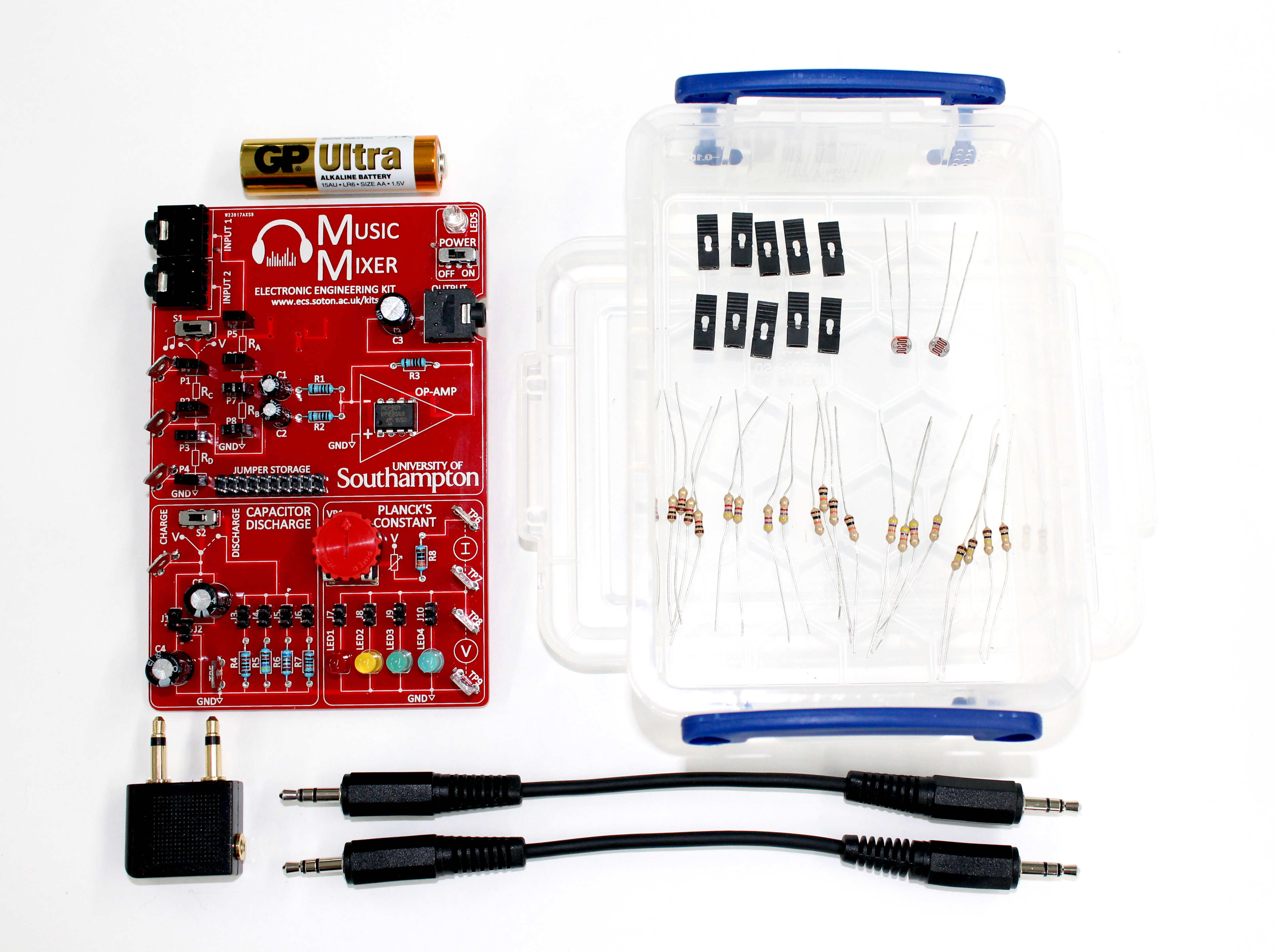
The music mixer kit combines two audio signals, for example music from mobile phones, enabling users to control the volume by experimenting with different electronic components, learn about electronic sensors (e.g. LDRs) and resistor dividers.
The design aims to expose all components and demystifies electronics for students.
The board also has dedicated sections for determining Planck’s constant – by measuring and plotting the voltage and current through four differently coloured LEDs – and experimenting with capacitor discharge.
The kit is currently not available to purchase, but limited numbers are being provided to schools for free. Schools/colleges interested in receiving kits, or organisations interested in sponsoring the scheme, can join our mailing list to find out more.
We are building teaching resources around these boards, for example our online training video. If you would like to contribute resources, please contact us.
The students have really enjoyed using them and exploring independently
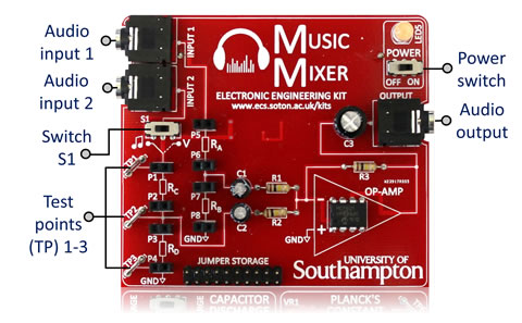
This introduces potential dividers using an audio mixer circuit. The board has two audio input channels that are mixed together using an amplifier. The volumes of the two channels are controlled by potential dividers where the resistor values can be changed or exchanged with LDRs, or other resistive elements, to control the level of each channel.
This tutorial video walks viewers through the typical use of the Music Mixer and the experiment described in the accompanying exercise notes.
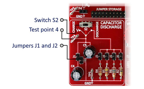
This allows students to explore the discharging of series and parallel capacitors through different resistances. Jumpers J1 and J2 allow the capacitors to be connected in series or parallel.
This tutorial video walks viewers through the typical use of the Capacitor Discharge Section part of the kit, and the experiment described in the accompanying exercise notes.
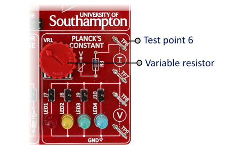
This allows students to estimate Planck’s Constant by measuring the voltage and current characteristics of a range of different colour light emitting diodes (LEDs). A spreadsheet is provided for students to enter measured values, and estimate Planck’s Constant.
This tutorial video walks viewers through the typical use of the Planck’s Constant part of the kit, and the experiment described in the accompanying exercise notes.
The kit really allowed me to focus in on the lesson as it removes the set up … The students were engaged as they have never experienced of this type of Electronics before. The results they get are fantastic
The videos below enable you to find out more about the Music Mixer kit, and the electronic engineering principles that make it work.
This video explores the potential dividers on the Music Mixer kit, how they are used to mix the two input channels, and the wider applications of this technology.
This video explores the functionality of an operational amplifier, how it is used in the Music Mixer kit, and some of the other uses of this widely used electronic component.
This video explores the OpAmp on the Music Mixer kit, and its configuration as a summing amplifier.
This board is brilliant – I love it and know it is a fantastic piece of kit
To provide training to teachers who were not able to travel to the University to attend one of our CPD workshops, we have recorded a dedicated video to provide some additional guidance.
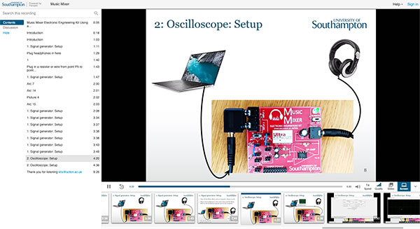
The video guides users through the process of connecting the Music Mixer Electronic Engineering Kit to a computer, using the computer as a signal generator and oscilloscope, and using it to demonstrate the interference of waves.
If the Music Mixer does not work, first of all:
If the Music Mixer still does not work then please email us.
These community-created resources have been developed by teachers while using the kit with their students, and are made available to support teaching and learning activities. The content has not been checked or verified by the UKESF or the University of Southampton. Teachers should verify the correctness of the content and suitability for their students/syllabus before using.
The University cannot accept responsibility for external websites.
It is essential that we maintain student engagement in Physics and Computer Science at A-Level as these are the gateway to engineering, hence our interest in working with UKESF and the University of Southampton to support teachers to inspire students’ interest in these subjects.
Sponsor
Supporter
Supporter
Supporter
Supporter
Supporter
Supporter
Donor
Donor
Donor
Donor
Donor
Donor
Donor
Donor
Donor
Donor
Donor
Donor
Donor
Donor
Donor
Donor
Donor
Donor
Donor
Donor
Electronics and technology play a vital role in tackling society’s biggest challenges, but at the moment, not enough young people have the opportunity to experience these subjects in an engaging way, or consider what career opportunities they could lead to.
The A-Level Physics Music Mixer Kit has been created by the following team from the University of Southampton and UK Electronics Skills Foundation:

Daniel is a Lecturer in ECS, and is leading the development of the A-Level Physics kits.

Alex is a Lecturer in ECS, and is leading on professional development activities using the A-Level Physics kit.

Geoff is a Professor and Director of Outreach in ECS, and founded the A-Level Physics kit project.

Stewart is the CEO of the UK Electronics Skills Foundation, and has led on securing funding to get the kits into schools.
For information on when kits are available, and other developments in the project, please join our mailing list.
For any other enquiries, or to contribute resources, please email kits@soton.ac.uk.
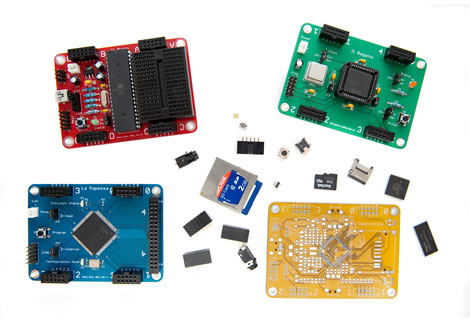
Four undergraduate-level teaching boards designed for Southampton students to gain experience with common processing elements, enabling them to quickly prototype their ideas.
Read more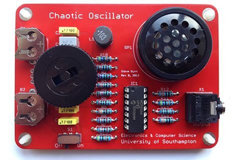
An introduction to soldering and, once completed, allows you to explore chaos theory through waves and sound.
Read more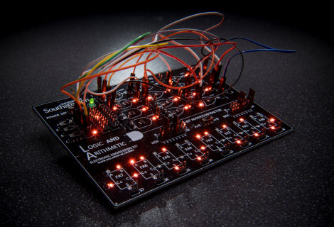
Designed to support the teaching of electronics topics in the A-Level Computer Science syllabus, from logic gates and Boolean algebra to binary numbers and arithmetic.
Read more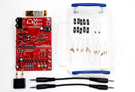
Designed to support the teaching of electronics topics of the A-Level Physics syllabus, from resistance and capacitance to waves and interference.
Read more
Designed to support the teaching of electronics topics of the A-Level Physics syllabus, from resistance and capacitance to waves and interference.
Read more
Designed to support the teaching of electronics topics in the A-Level Computer Science syllabus, from logic gates and Boolean algebra to binary numbers and arithmetic.
Read more
An introduction to soldering and, once completed, allows you to explore chaos theory through waves and sound.
Read more
Four undergraduate-level teaching boards designed for Southampton students to gain experience with common processing elements, enabling them to quickly prototype their ideas.
Read moreFor information on when kits are available, and other developments in the project, please join our mailing list.
For any questions or enquiries about these kits, please contact us at kits@soton.ac.uk
Dr Themis Prodromakis from the University of Southampton has been awarded a Royal Society Industry Fellowship to progress the development of bioelectronics that would revolutionise the treatment of nervous system disorders.
The four-year fellowship, a collaborative partnership with pharmaceutical company GlaxoSmithKline (GSK), will exploit the potential of memristive devices across an ambitious programme from September 2017.
The project aims to deliver a platform technology that will address the current limitations placed on implantable neural devices by bandwidth and power constraints. The advance would enable the integration, analysis and interpretation of data in real-time while requiring minute power and chip area.
Themis, an Engineering and Physical Sciences Research Council (EPSRC) Fellow and Reader in Nanoelectronics at the Universityâs Department of Electronics and Computer Science (ECS), commented: âIâm delighted to receive this prestigious award that will allow me to translate some of the key fundamental scientific research contributions I have developed over the past four years with the support of the EPSRC and the EU, addressing some of the outstanding challenges of neural interfaces in the field of bioelectronics. This partnership between the University of Southampton and GSK will combine emerging technologies in a new application space: the bioelectronics initiative.â?
The Industry Fellowship will focus on memristive devices that appear well-suited to providing a disruptive technological boost by performing the role of artificial synapses.
Themis explained: âMuch akin to biological synapses, these memristive devices possess the intrinsic ability to simultaneously carry out computational tasks and store information at aggressively downscaled volumes and power dissipation. In this front, we recently demonstrated in an article in Nature Communications that the intrinsic characteristics of solid-state nanoscale memristors, such as input thresholding and analogue modulation of resistive state, can be used to encode neuronal spiking activity while suppressing noise.
âThrough this award we aim to exploit this concept for building a highly scalable integrated neural activity decoder. The availability of such a technology would revolutionise the development of embedded devices for treating a wide variety of nervous system disorders.â?
Researchers at Southampton have also recently secured funding from the Innovation to Commercialisation (ICURe) programme to help define commercialisation strategies for the technology. The Universityâs Faculty of Physical Sciences and Engineering has invested in three patents in the area and will seek to benefit from expertise within GSK as it steers activities to maximise impact.
The University cannot accept responsibility for external websites.
